
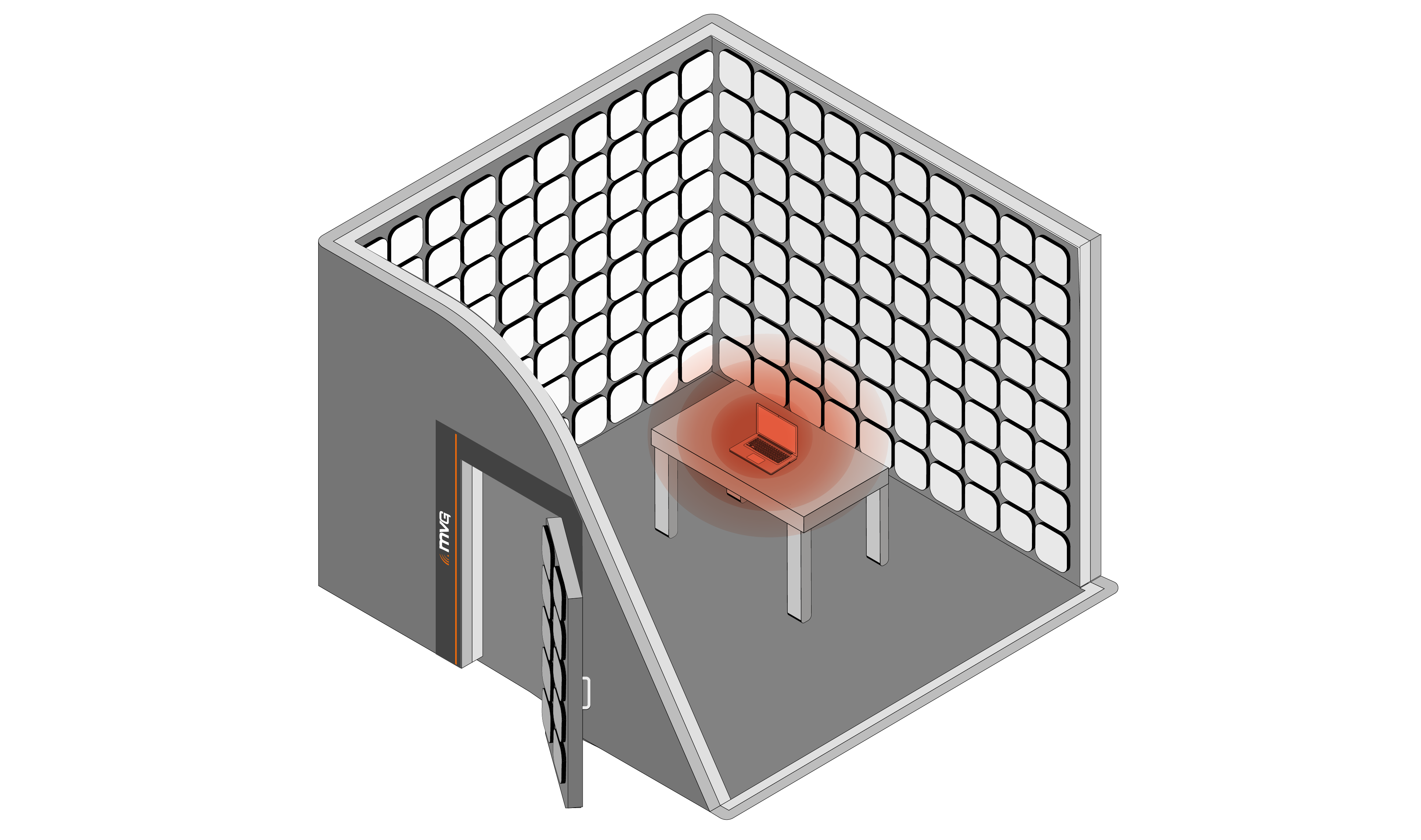
 EMC emissions testing is widely regarded as the most pivotal aspect of electromagnetic compatibility (EMC) evaluation—often determining whether a product can be legally certified for market release. Nearly every region across the globe enforces strict standards for radiated emissions, though these limits can vary significantly depending on the product's application and intended environment.
Regardless of location, radiated and conducted emissions evaluation is a fundamental requirement in most major markets. It also happens to be the most frequently failed portion of EMC compliance, underscoring its complexity and importance.
In the European Union, the EMC Directive 2014/30/EU and Radio Equipment Directive (RED) 2014/53/EU mandate emissions compliance, while similar regulatory frameworks exist worldwide through FCC regulations (United States), VCCI standards (Japan), and CCC requirements (China).
This comprehensive guide explores the essentials of EMC emissions, including:
Key Points :
- Radiated emissions evaluation: Measuring electromagnetic energy emitted through space
- Conducted emissions assessment: Evaluating interference transmitted via cables
- Practical preparation strategies to boost certification success rates
- EMC emissions testing measures both radiated (through air) and conducted (through cables) electromagnetic energy
- Radiated emissions occur when conductors act as antennas, transmitting electromagnetic waves into the environment
- Conducted emissions travel along cables and wiring, potentially affecting connected equipment
- Testing environments include semi-anechoic chambers (SACs) and Open Area Test Sites (OATS)
- Emissions testing has the highest failure rate among all EMC evaluations, requiring careful design and preparation
- Compliance with the EMC Directive and regional standards is mandatory before market release
Understanding EMC Emissions: Radiated vs Conducted
The Two Categories of Electromagnetic Emissions
Every electrical and electronic device generates electromagnetic emissions, which fall into two primary categories: radiated and conducted. Understanding this distinction is essential for designing compliant products and preparing for evaluation.
Radiated Emissions Explained
Radiated emissions occur when a non-DC signal energizes a sufficiently long conductor, effectively turning it into an antenna. This conductor then transduces electrical signals into electromagnetic waves, which radiate into the surrounding environment.
Common sources of radiated emissions include:
Switching supplies with rapid voltage transitions
Digital circuitry including processors, memory, and logic gates
AC transmission within a device
Signal generators such as oscillators or resonators
High-speed data buses and communication interfaces
These emissions can interfere with nearby devices, especially in environments dense with electronics such as hospitals, data centers, or industrial facilities. The EMC Directive specifically addresses these concerns by establishing essential requirements for emission control.
Conducted Emissions Explained
Conducted emissions differ in that they travel along conductive paths, such as cables or communication lines, rather than radiating through the air. These emissions are typically injected into nearby wiring—especially supply cords or signal lines—through capacitive or inductive coupling.
Conducted emissions can:
Affect other equipment connected to the same electrical circuit
Propagate back into the electrical grid, potentially disturbing sensitive equipment elsewhere
Convert to radiated emissions when cables act as unintentional antennas
Cause compliance failures even when the device itself has good internal EMC design
Understanding the distinction between radiated and conducted emissions is essential for designing compliant equipment and preparing for EMC evaluation under the EMC Directive and other regulatory frameworks.
Radiated Emissions Testing: Methods, Environments, and Standards
Purpose and Regulatory Context
Radiated emissions evaluation is a cornerstone of EMC compliance, designed to measure the electromagnetic energy unintentionally emitted by electronic devices. Due to the need for consistent, accurate, and repeatable results, this evaluation is conducted in highly controlled environments.
Testing Environments
The most widely accepted and standardized environments are:
Semi-Anechoic Chambers (SACs)
Most prevalent and accessible option in modern EMC laboratories
Absorptive walls and ceiling lined with RF-absorbing material
Reflective ground plane simulating real-world installation conditions
Controlled electromagnetic environment free from external interference
Weather-independent operation allowing year-round evaluation
Open Area Test Sites (OATS)
Outdoor facilities with minimal RF interference
Large open spaces meeting specific geometric requirements
Ground plane construction to control reflections
Less common today due to weather sensitivity and ambient RF pollution
Still specified in some standards for reference measurements
While other setups exist, SACs and OATS are the most widely accepted, with SACs being the preferred choice for commercial laboratories due to their reliability and availability.
Test Setup and Procedure
In a semi-anechoic chamber:
The Equipment Under Test (EUT) is placed on a motorized turntable, allowing it to be rotated 360° during measurement. A measurement antenna is positioned at a fixed distance and height, typically 3 meters or 10 meters depending on the standard. The antenna captures emissions from all angles of the EUT, accounting for directional radiation patterns. The antenna is connected to a spectrum analyzer or EMI receiver capable of sweeping across the regulated spectrum range. Field strength is recorded at each critical point across the specified bandwidth
This setup accounts for the directional nature of some emissions, which may not radiate uniformly from the device. Some emissions may be strongest from specific angles or when the device is oriented in particular directions.
Emissions Reporting and Compliance Determination
After a full scan, the evaluation generates a radiated emissions report, which includes:
Measured field strength across the spectrum with peak, quasi-peak, or average detection
Graphical representation showing emissions relative to limit lines
Comparison against regional or application-specific emission limits as specified by the EMC Directive, FCC regulations, or industry standards
Identification of specific frequencies where emissions approach or exceed limits
Pass/fail determination for each applicable standard
Compliance is determined by whether the emissions fall below the allowable thresholds for the region or industry in question.
Regional and Application-Based Variations
Radiated emissions limits vary significantly based on:
Geographic Region
- European Union: Governed by the EMC Directive 2014/30/EU with harmonized standards like CISPR 32, EN 55032
United States: FCC Title 47 Part 15 with Class A (industrial) and Class B (consumer) distinctions
Japan: VCCI standards aligned with CISPR requirements
China: GB standards implementing similar limits with regional variations
Application or Industry Sector
Consumer electronics typically face stricter limits than industrial equipment due to residential use proximity. The FCC often defines the upper limit based on the highest internal clock rate of the device.
Specialized sectors follow their own stringent standards:
Military: MIL-STD-461 with significantly tighter limits and extended ranges
Aerospace: RTCA/DO-160 for avionics with altitude and environmental considerations
Automotive: CISPR 25 with vehicle-specific test configurations
Railway: EN 50121 series addressing rail-specific electromagnetic environments
These specialized standards differ significantly from general commercial EMC requirements and must be addressed accordingly during product development and evaluation.
Conducted Emissions Testing: Ensuring Compliance at the Power Interface
Understanding Conducted Emissions
Conducted emissions are an inevitable byproduct of electronic equipment, especially when cabling—such as a DC supply cord—is directly connected to a device. These emissions represent electromagnetic energy that travels along conductive paths and can be injected back into the electrical grid, potentially causing instability or triggering radiated emissions that exceed regulatory limits.
Purpose and Spectrum Coverage
Conducted emissions evaluation ensures that the level of interference conducted into lines remains within acceptable limits. These assessments typically focus on the 150 kHz to 30 MHz range, where conducted noise is most likely to affect other installations.
The EMC Directive and harmonized standards like CISPR 32 / EN 55032 specify precise limits for conducted disturbances in this spectrum range, with different classes for residential vs. industrial environments.
Test Setup: LISNs and Measurement Equipment
Evaluation is performed using a Line Impedance Stabilization Network (LISN) also known as:
Artificial Network (AN)
Artificial Mains Network (AMN)
The LISN is placed between the Equipment Under Test (EUT) and its supply source. It serves two key functions:
Presents a known impedance to the EUT, ensuring consistent conditions regardless of the actual electrical grid characteristics isolates unwanted RF signals from the source while channeling them to a spectrum analyzer via an RF port
To protect sensitive measurement equipment, LISNs often include transient surge protection. The LISN essentially creates a standardized electrical environment that makes test results repeatable and comparable across different laboratories.
Measurement Process
During conducted emissions evaluation:
The LISN connects to both line and neutral conductors (and protective earth where applicable)
A spectrum analyzer sweeps the 150 kHz to 30 MHz range, measuring voltage levels at the LISN's RF output
Both quasi-peak and average detectors are typically used, as specified in CISPR 16 measurement standards
Results are compared against applicable limits from the EMC Directive harmonized standards or regional equivalents
Common Failure Points and Mitigation Strategies
Conducted emissions failures are frequent, and switching supplies are a common culprit—even those that are pre-certified. Failures may arise due to:
- Differences between how the supply was originally evaluated and how it operates in your installation
- Manufacturing inconsistencies between supply batches
- Incompatibility with the EUT's electrical behavior, particularly input capacitance or load characteristics
- Inadequate filtering in the final product configuration
- Cable routing and grounding affecting common-mode emissions
Best Practices for Passing Conducted Emissions
To improve the likelihood of compliance:
Choose supplies carefully, considering both certification and real-world performance in similar applications
Test with multiple supply models to identify the best fit for compliance before committing to production
Verify compatibility between the supply and your device under actual operating conditions
Implement additional filtering if necessary, even with pre-certified supplies
Control cable routing to minimize common-mode current paths
Conduct pre-compliance assessment during development to identify issues early
Document supply specifications and test configurations for technical files required by the EMC Directive
Preparing for EMC Emissions Testing Success
Design Considerations for Lower Emissions
Reducing emissions at the source is more effective than attempting to fix problems after prototype evaluation:
PCB Layout Best Practices:
- Minimize loop areas in high-current paths
- Use ground planes to provide low-impedance return paths
- Control trace impedance for high-speed signals
- Separate analog and digital sections where practical
- Route clock signals carefully with controlled impedance and minimal stubs
Filtering and Shielding:
- Implement input filtering on all external connections
- Use ferrite beads on cables to suppress common-mode currents
- Apply shielding to enclosures when necessary
- Ensure proper grounding of shields and chassis
Pre-Compliance Evaluation
Conducting pre-compliance assessment during development:
- Identifies potential issues early when fixes are less expensive
- Allows iterative design improvements before formal certification
- Significantly improves first-time pass rates at accredited laboratories
- Reduces overall time-to-market despite the additional upfront effort
Choosing the Right Test Laboratory
Select an accredited laboratory that:
- Holds appropriate accreditations (ISO/IEC 17025, A2LA, UKAS, etc.)
- Has experience with your product type and target markets
- Understands the EMC Directive and other applicable regulatory frameworks
- Offers pre-compliance services for development support
- Can test to multiple regional standards if needed for global markets
Frequently Asked Questions
What is EMC emissions testing?
EMC emissions testing measures the electromagnetic energy that electronic devices unintentionally emit, either through the air (radiated emissions) or through connected cables (conducted emissions). This evaluation verifies compliance with the EMC Directive in Europe, FCC regulations in the United States, and similar standards worldwide, ensuring devices don't cause harmful interference to other equipment.
What's the difference between radiated and conducted emissions?
Radiated emissions are electromagnetic waves that propagate through space from the device, typically from conductors acting as unintentional antennas. Conducted emissions travel along cables and wiring connected to the device, particularly through supply cords. Both types must be evaluated separately using different test setups and equipment to ensure full EMC compliance under the EMC Directive.
Why do so many products fail emissions testing?
Emissions evaluation has the highest failure rate in EMC compliance because:
Design teams often overlook EMC until late in development
Switching supplies can generate unexpected emissions
Cable routing and grounding significantly affect results but are hard to predict
Pre-certified components may behave differently in your specific application
High-speed digital circuitry creates harmonics that extend into regulated ranges
Early attention to EMC design principles dramatically improves success rates.
What equipment is used for emissions testing?
For radiated emissions:
Semi-anechoic chamber or OATS facility
Calibrated measurement antennas (broadband or tuned)
Spectrum analyzer or EMI receiver
Motorized turntable for the Equipment Under Test
For conducted emissions:
Line Impedance Stabilization Networks (LISNs/AMNs)
Spectrum analyzer or EMI receiver
RF cables and appropriate adaptors
All equipment must be calibrated and traceable to national standards.
How long does emissions testing take?
Typical duration varies by product complexity:
Simple consumer products: 4-8 hours for both radiated and conducted
Complex industrial equipment: 1-2 days for complete emissions evaluation
Products with multiple configurations: Additional time for each mode
Pre-compliance assessment typically requires similar durations but in a less formal environment.
What frequency ranges are tested?
Radiated emissions typically cover:
30 MHz to 1 GHz for most commercial products (per EMC Directive harmonized standards)
Extended ranges up to 6 GHz or higher for devices with high-speed digital components or wireless functions under the Radio Equipment Directive
Conducted emissions typically cover:
150 kHz to 30 MHz for mains-connected equipment
Specialized standards (military, automotive, aerospace) may specify different ranges.
How much does emissions testing cost?
Costs vary widely based on:
Product complexity: ,000-,000 for basic commercial products
Testing standard requirements: Military or aerospace standards cost significantly more
Laboratory location and accreditations
Number of configurations to be evaluated
Pre-compliance assessment during development adds ,000-,000 but often saves money by preventing failures.
Can I do pre-compliance emissions testing myself?
Yes, with appropriate equipment you can conduct pre-compliance assessment during development. Basic setups require:
Near-field probes or measurement antennas
Spectrum analyzer (can be rented)
LISN for conducted emissions
Understanding of measurement techniques
However, formal certification requires accredited third-party laboratories to comply with the EMC Directive and other regulatory frameworks.
What are the emission limits for my product?
Limits depend on several factors:
Geographic market: Different limits apply under the EMC Directive (Europe), FCC (USA), etc.
Product classification: Consumer (Class B) vs. industrial (Class A)
Industry sector: Medical, automotive, military have specific requirements
Consult harmonized standards like EN 55032/CISPR 32 or work with an EMC test laboratory to identify applicable limits.
What happens if my product fails emissions testing?
Upon failure, you'll receive a detailed report showing exactly which emissions exceeded limits and at what locations. You must then:
Analyze failure modes (specific components, cables, or design issues) Implement design changes (improved filtering, shielding, layout modifications) Conduct pre-compliance verification of fixes Resubmit for formal evaluation
Each retest cycle adds cost and delays market launch, emphasizing the importance of pre-compliance work.
Key Recommendations for Emissions Testing Success
To maximize your chances of passing EMC emissions evaluation:
- Design for EMC from day one - Integrate emissions control into initial design phases, not as an afterthought
- Conduct iterative pre-compliance assessment - Test throughout development to catch issues when fixes are inexpensive
- Pay special attention to supply selection - Pre-certified supplies don't guarantee compliance in your application
- Implement proper PCB layout - Minimize loop areas, use ground planes, control high-speed signal routing
- Control cable routing and shielding - Cables are often the dominant source of radiated emissions
- Understand applicable standards - Know whether you're targeting the EMC Directive, FCC regulations, or specialized industry standards
- Budget adequate time and resources - Plan for potential redesigns and retesting in your project schedule
- Engage EMC experts early - Consultants and test laboratories can review designs before committing to production
- Document your compliance process - Maintain technical files demonstrating conformity with the EMC Directive and other frameworks
EMC emissions testing is challenging, but with proper preparation, design discipline, and iterative assessment, you can significantly improve your first-time pass rate and accelerate your path to market certification. Understanding both radiated and conducted emissions principles—and how they're evaluated under the EMC Directive and regional standards—is essential for developing compliant, interference-free products.
Topic overview