Absolute Antenna Gain Measurement Methods
- Reference gain (Comparison) method
Requires gain standard (gain is known within a specified accuracy)
- Two-antenna gain measurement
Direct gain measurement (gain by insertion loss)
Identical antenna gain measurement
- Three-antenna method
Does not require identical antennas
Measurements for all possible pair combinations
Yield gain of all three antennas
+ Gain derived from directivity results
A non-existent isotropic radiator is used to define absolute gain units. But once defined, how is absolute gain measured? One of three methods can be used: the reference (comparison) method, the two- antenna gain measurement, and the three-antenna method. Gain can also be empirically calculated from directivity results, provided the impedance loss mismatch is also known.
Gain Standards
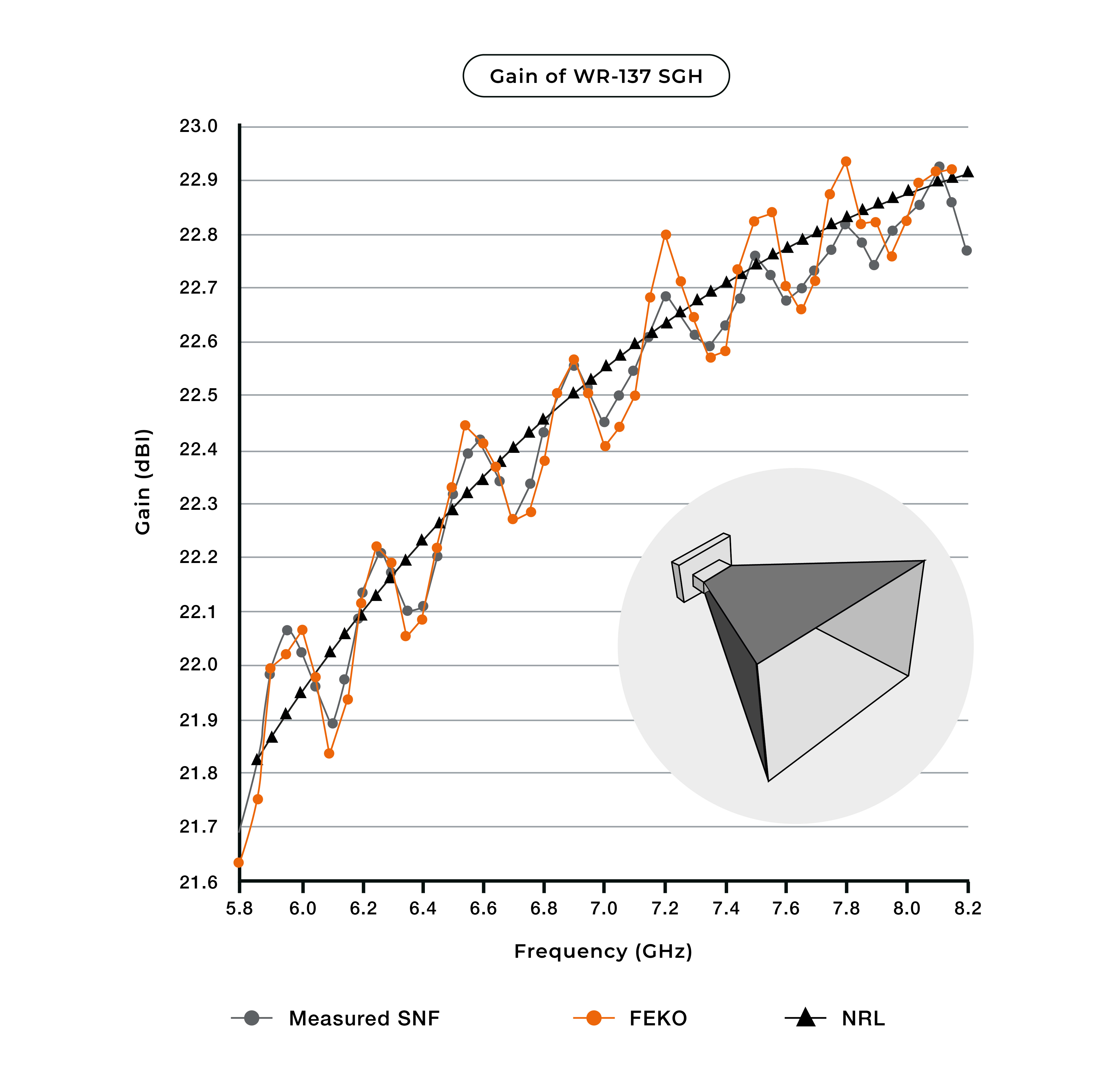
- In microwave frequency bands, rectangular horns are commonly used as gain standards.
- The gain is almost equal to the directivity given by the manufacturer.
- NRL gain curves are typically accurate to within 0.3- 0.5 dB of actual gain
- If higher accuracy is required, it is necessary to calibrate the gain standard
- Integrate the radiation patterns to obtain the directivity and measure the reflection and ohmic losses
- Obtain an absolute gain measurement provided by NMI or calibration lab
Gain Reference Standards
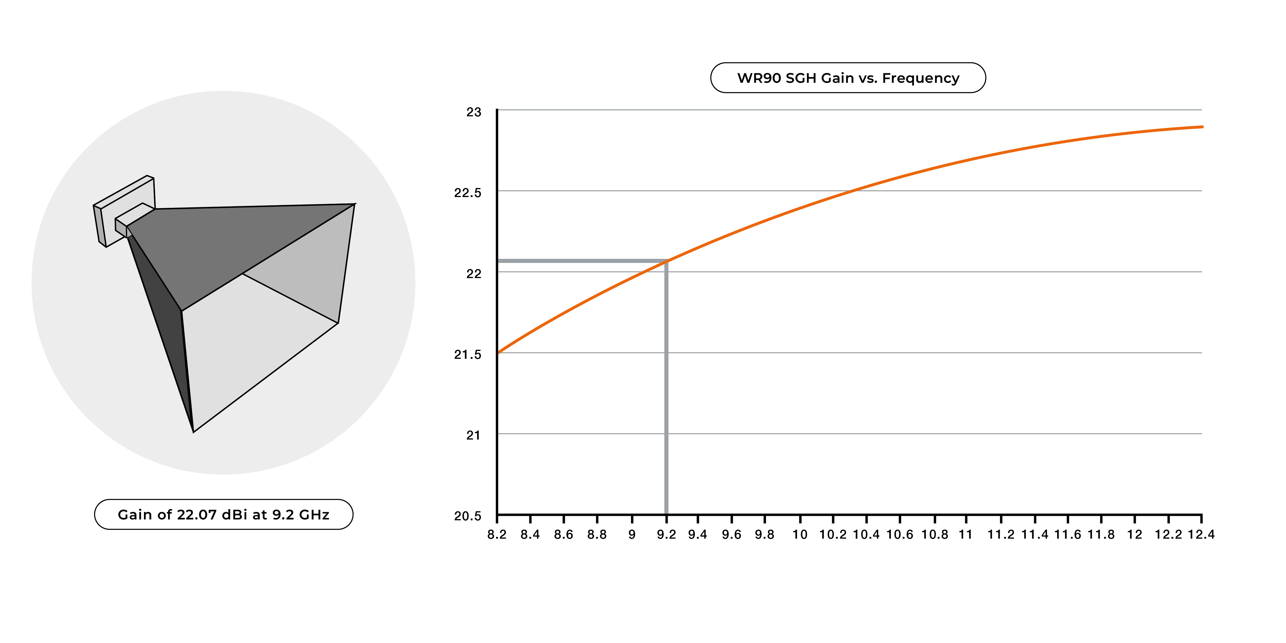
The reference gain method requires the use of a ‘known” gain standard used to normalize the measured test antenna to absolute units. Gain reference standards are commercially available and typically come with gain data based on the manufacturer specifications. As a result, the manufacturing tolerances typically limit the accuracy of this data to within +/‐0.3 to +/-0.5 dB, depending on the frequency range. From a measurement uncertainty perspective, this means one should never expect to achieve gain measurement accuracies less than that of the standard being used.
So what if better gain measurement accuracy is required? Alternatively, you can choose to have your gain standard antenna calibrated by a certified calibration laboratory, which can provide measured gain data uncertainties in the range of +/‐0.1 to +/‐0.25 dB. This can be a costly endeavor where price is driven by the desired uncertainty.
Gain Comparison Method
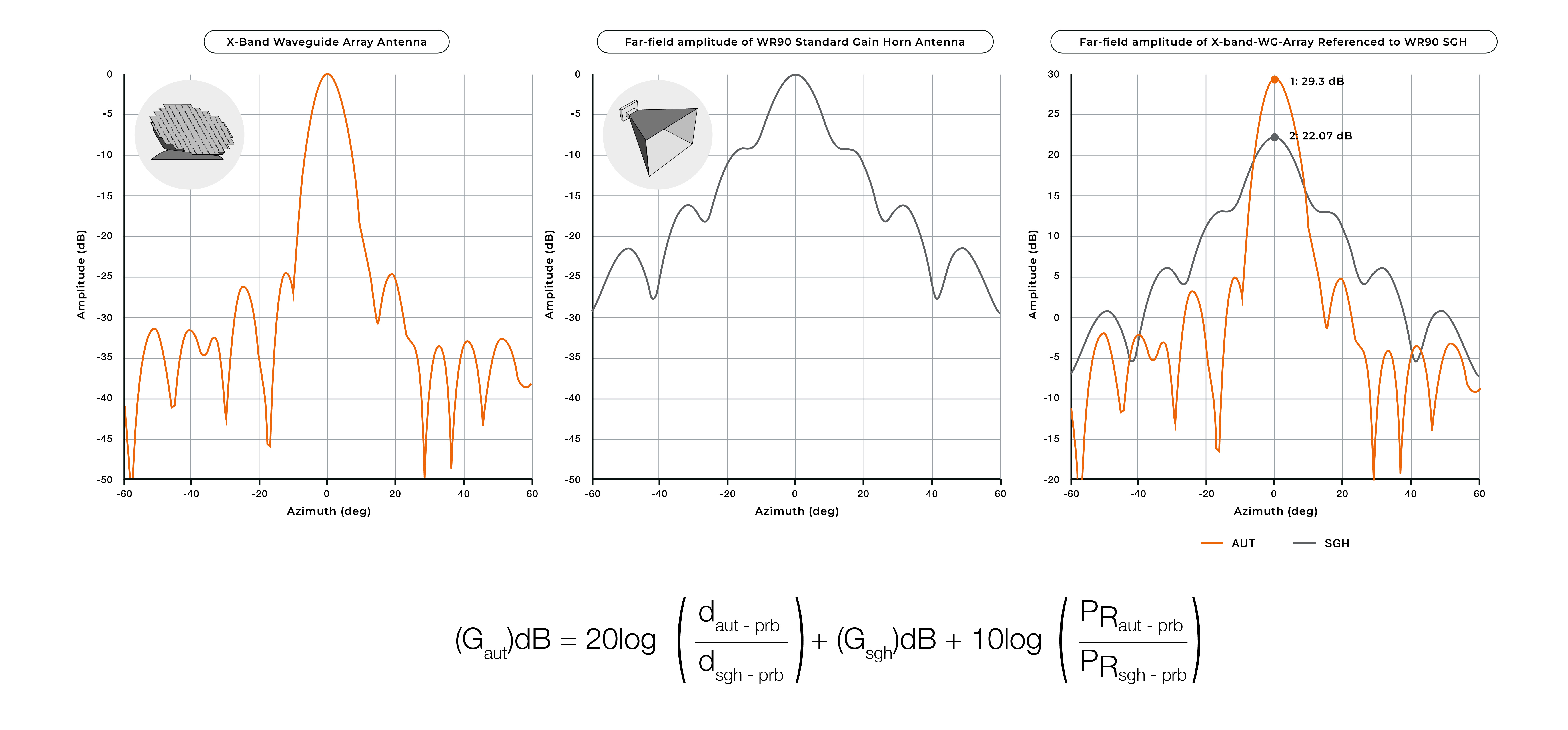
The Gain Comparison Method involves making individual measurements of both the AUT and the gain standard using the same measurement configuration. The unnormalized difference between these two measurements and the “known” gain of the standard is then used to determine the AUT gain in absolute dBi units.
During the measurement process, care must be taken when replacing the AUT with the gain standard to minimize the introduction of additional measurement errors such as impedance mismatch. The same RF cable should be used to connect both the AUT and the gain standard. If an additional RF component(s), such as an adapter, is required, then the insertion loss of this device must be included in the normalization constant.
Direct Gain Method
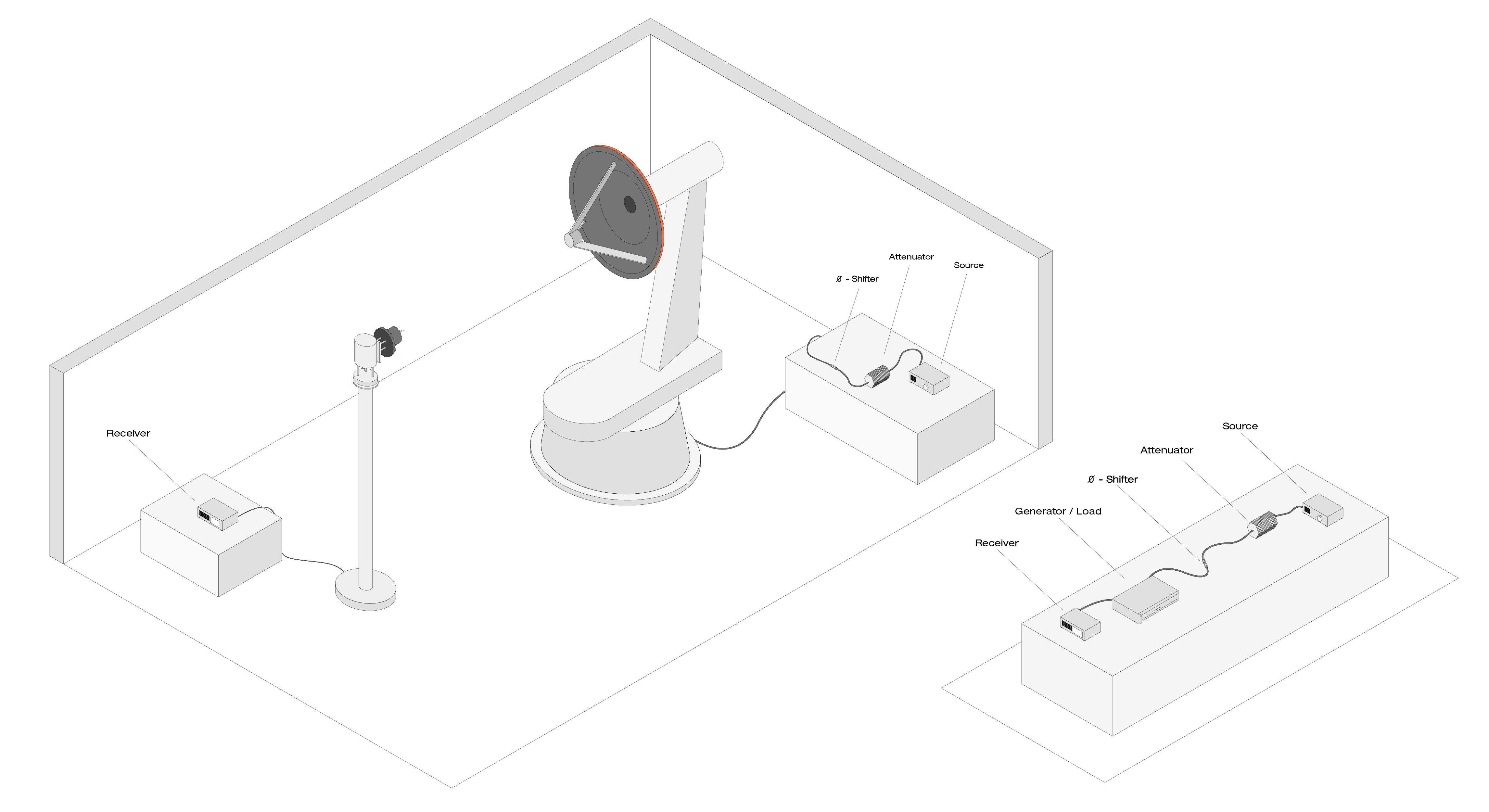
- Probe is the gain standard: Probe gain must be known
- Measurements performed only on the AUT
- AUT input cable then connected to probe output cable and receiver amplitude recorded
- Attenuator may be used to reduce signal level at mixer
- Substitution cable with known loss may be necessary for large separation distances
The Gain Comparison Method can be used on any type of antenna measurement system. However, in a near-field measurement system, this requires making a complete near-field scan of both the AUT and the gain standard. A more expedient (and accurate) method of measuring gain in this type of system is the Direct Gain Method.
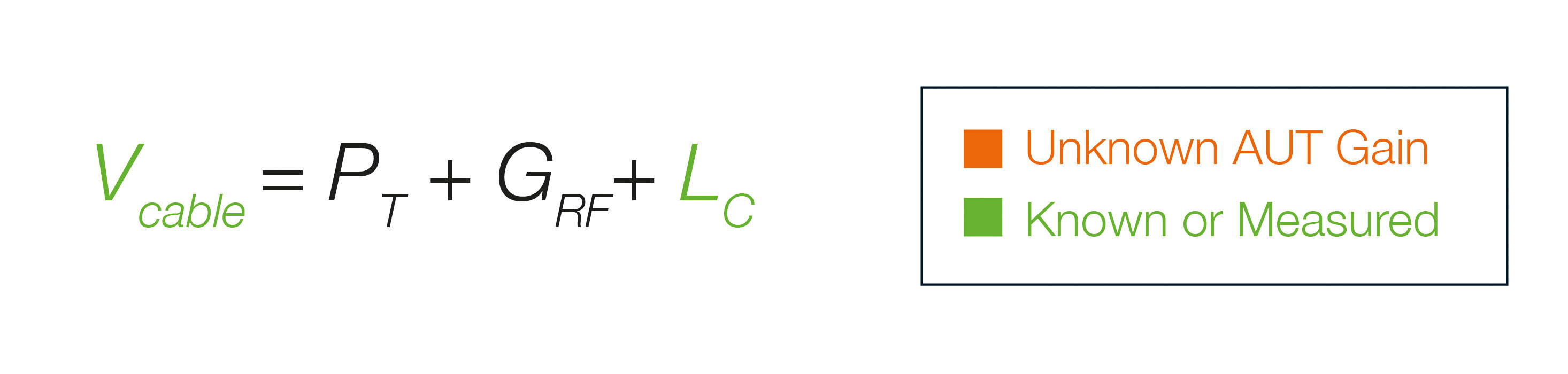
This method is commonly used in near-field measurement systems and is similar to the Gain Comparison Method in that the AUT gain is determined from the “known” gain of another antenna. In this case, the “known” antenna is the near-field probe itself. Unlike the Gain Comparison Method, this technique does not require making two separate antenna measurements. Instead, a single swept frequency measurement is made with the AUT RF cable connected directly to the probe RF cable, bypassing both the AUT and probe. Typically, a “known” attenuator representative of the free space loss is used when connecting the two cables to ensure that power levels remain relatively the same between the two measurements. This direct measurement, along with the known gain of the probe and attenuator, is then used to determine a normalization factor to convert the resulting AUT far‐field pattern to dBi units.
Again, the gain accuracy of this method is limited by the gain uncertainty of the probe. Commonly, the gain values of off-the-shelf probes are calculated based on the aperture size of the probe and can have uncertainties of +/- 0.5 dB or greater.
Two-Antenna Gain Method
- Similar to direct gain measurement, but the probe gain is unknown and assumed to be the same as the AUT gain
- Only useful for similar antennas
- Introduces additional error due to mismatch between gain values of antennas (manufacturing tolerance)
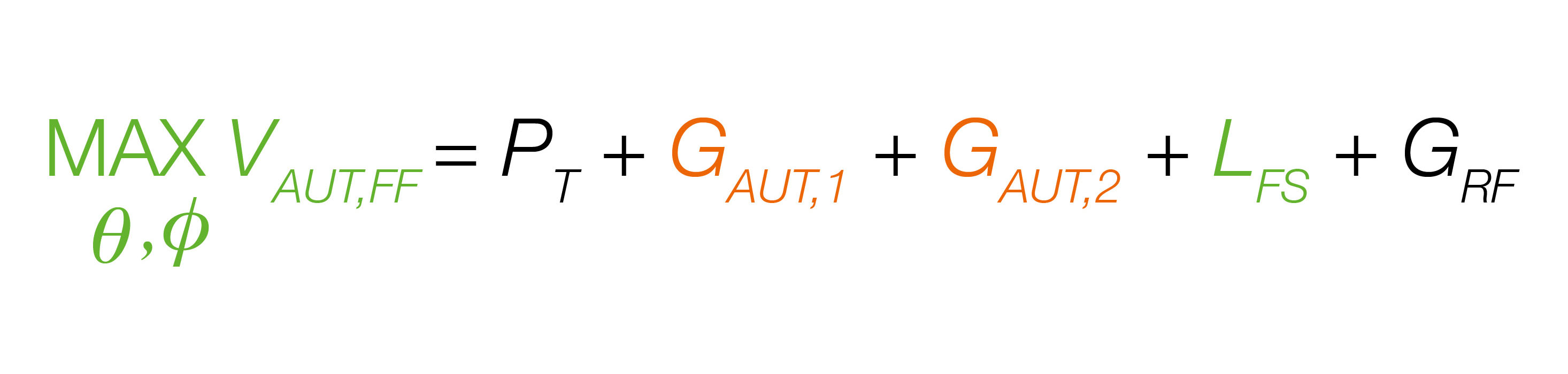

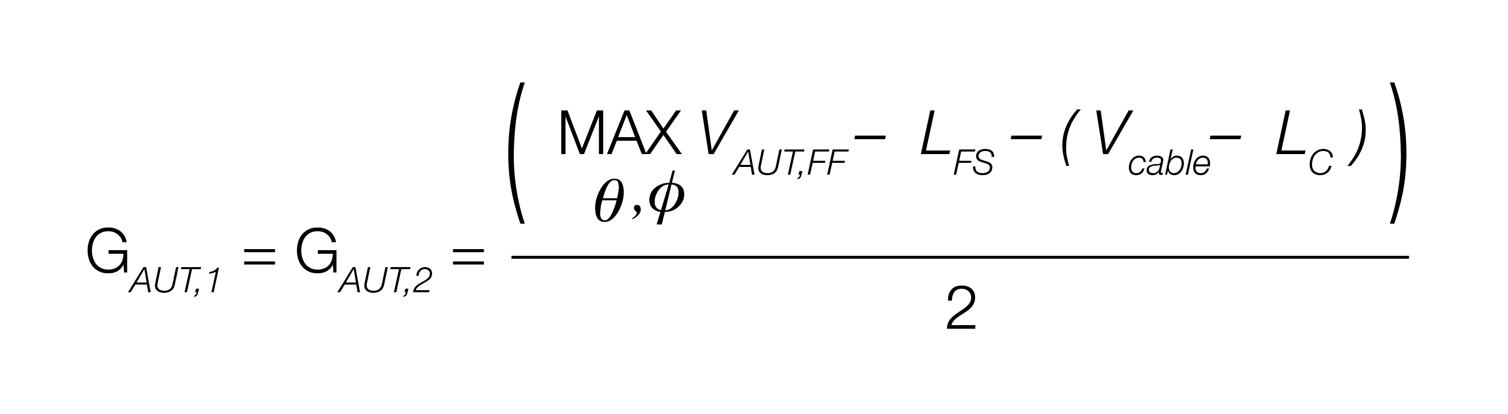
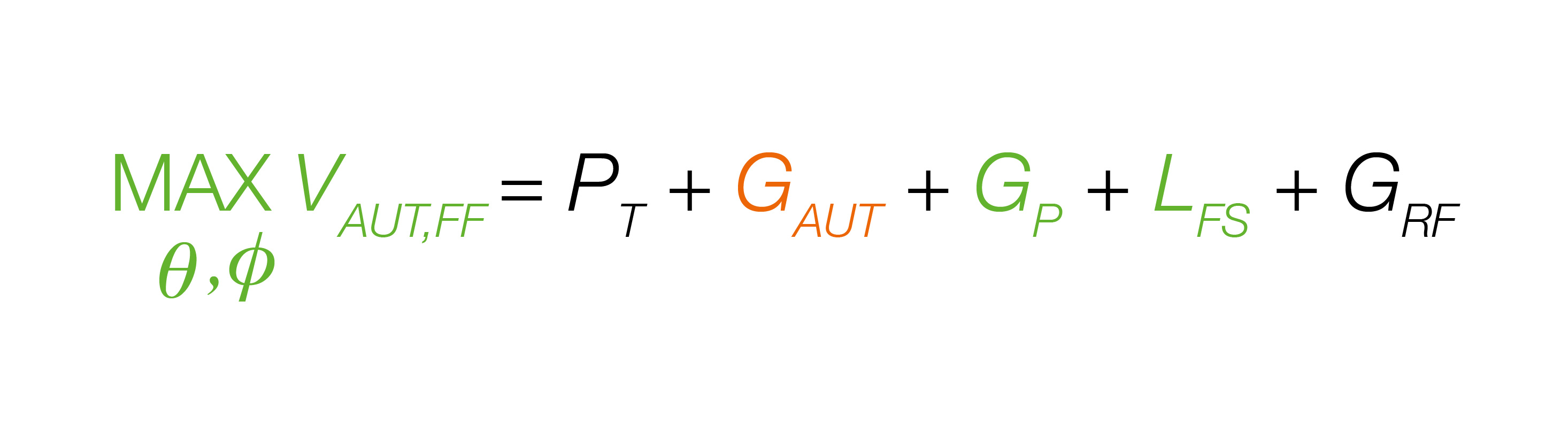
The Two-Antenna Gain Method is similar to the direct gain measurement, but in this case the probe gain is unknown and is assumed to be the same as the AUT gain. As this is typically not the case, this method is not as accurate as the other methods and is seldom
used.
Three-Antenna Gain Method
- Uses three antennas and gain standard
- Involves making three measurements and solving the three Friis equations for the gain of the three antennas
- Requires accurate knowledge of antenna phase center – especially with short range lengths
The Three-Antenna Gain Method is the most accurate gain measurement method used and but also the most labor-intensive. The beauty of this method is that it does not require knowing the gain for any of the three antennas. However, it does help if one of the antennas is gain standard for verification purposes. The method relies on the principle of solving three equations using three unknowns and requires making three separate measurements of all pair combinations. All three antennas must have the same or overlapping frequency bands, and the phase center of each antenna must be accurately known.
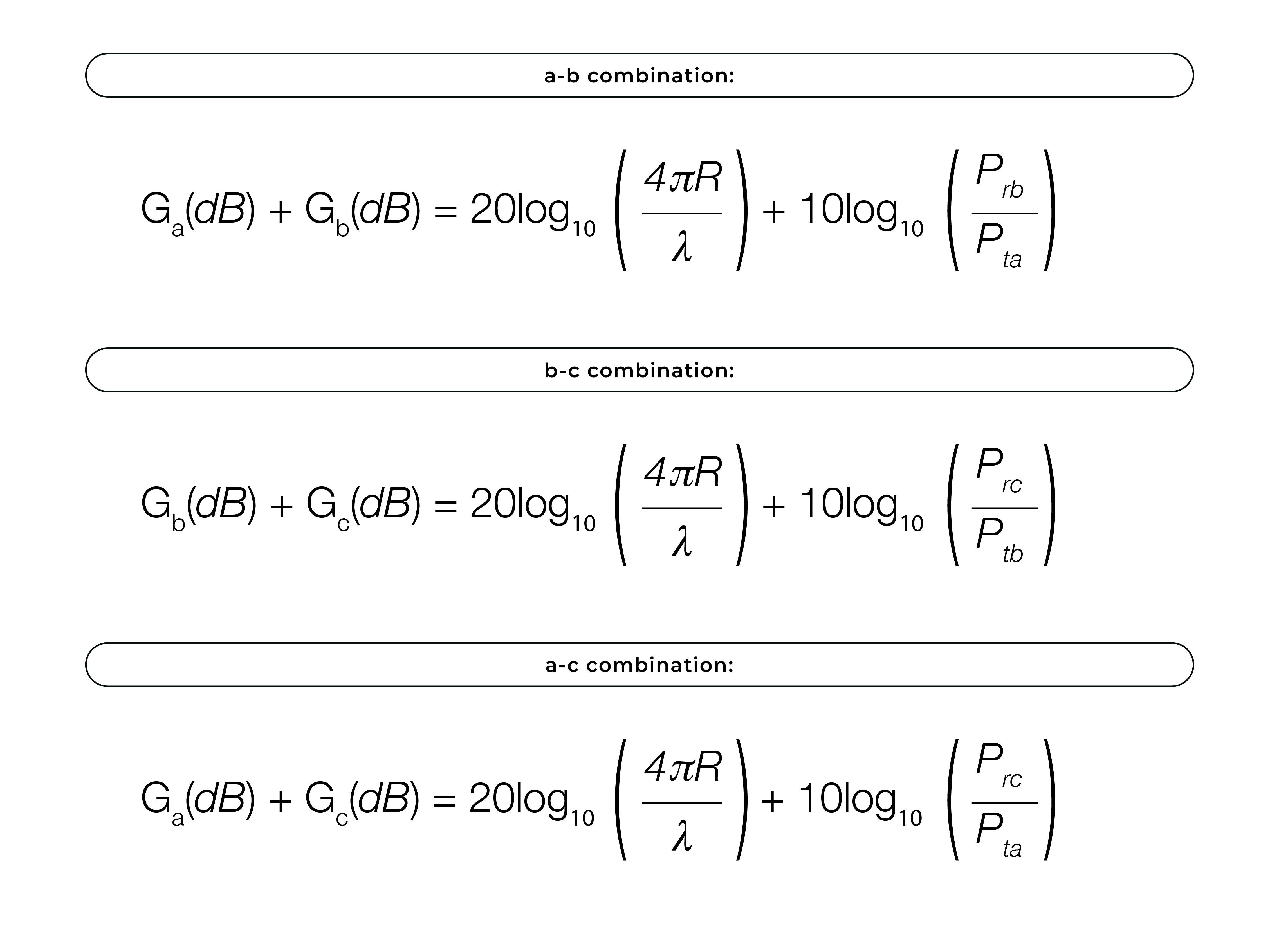 Solve the above simultaneously Ga(dB), Gb(dB), Gc(dB)
Troubleshooting Unreasonable Gain Results
- If gain is greater than directivity, verify the gain values for the gain standard
- Check for large multiple reflections or room scattering
- Check for loose connections and cable variances with movement
- Check the calibration of cables and switches used to change from AUT to gain standard
Making accurate gain measurements can be challenging and requires considerable effort. To ensure you're achieving good, reasonable results, there are a few things you can do to verify you're on the right track. Start by comparing the measured gain to the directivity. Keep in mind that directivity is a calculated value that does not account for mismatch and other losses affecting antenna efficiency, so the measured gain should always be lower than the directivity value. If it's not, there might be an issue with your measurement process.
Begin by checking the gain value selected for your standard. If this is correct, review your measurement setup. Common error sources that affect gain measurements include multi-path reflections, VSWR mismatch, RF leakage, and uncompensated network losses. Diagnostic measurements can help identify reflections, and additional pre- and post-measurement techniques can reduce this error. Be sure to inspect your measurement system for any loose RF connections and verify that the insertion loss of any components used between measurements has been compensated for correctly.
Topic overview